Introduction
This is a continuation of my previous article, Response Effects of Guitar Pickup Position and Width, and uses similar techniques to examine combinations of two and three pickups, various proportional mixes of the pickups, the special case of equal mixes, pickup polarity, mixes of three pickups, and includes equations and response plots.
Three pickups
The neck and bridge pickup combination
Analysis of a two pickup mix
Neck and bridge pickups, opposite polarity
Analysis of two pickups, opposite polarity
Middle pickup combinations
Three pickup combinations
Conclusion
Three pickups
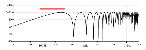
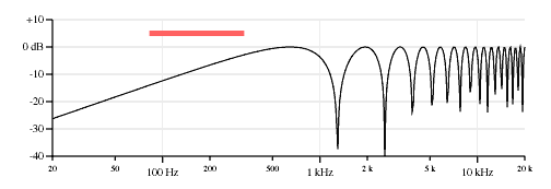
Figure 1 shows the frequency response curves of the low E string (82.4 Hz) for the neck, middle and bridge pickups on an example instrument very similar to a Fender Stratocaster using the equations, assumptions and nomenclature in the previous article. I use the Fender Stratocaster as an example because it is a remarkably popular instrument, I am personally very familiar with it, most readers will be able to relate to it, because it has three pickups, and because the pickups are in very typical locations. And if you ignore the middle pickup, the remaining pickups are in typical locations for a two pickup instrument.
Throughout this text all the plots are calculated for a scale length of 25.5 inches, the neck pickup located 6.375 inches from the bridge, the middle pickup located 3.875 inches from the bridge, the bridge pickup located 1.625 inches from the bridge. The idealized pickups in this article sense the string displacement velocity at a single point (ie., they have a magnetic aperture of zero) for more clarity in the response plots.

The neck and bridge pickup combination
Mixing the neck and bridge pickups is the most typical pickup combination for a two-pickup instrument. Figure 2 shows a response plot taking the algebraic average, or 50-50 mix of the neck and bridge pickups.
I should point out that on a guitar a pickup mix is typically implemented by shorting two pickups together with a switch. This is not a perfect mix as there is some interaction between the two pickups that occurs when they are shorted. I am ignoring that effect in this article.

The three-pickup Fender Stratocaster is often compared to the two-pickup Fender Telecaster. They are both classic instruments of similar design, with similar electronics and construction. The Telecaster was earlier, the first commercial solid body electric Spanish guitar in fact, and offers a choice of neck, neck&bridge and bridge pickups on a three-way switch. The Stratocaster originally offered a choice of neck, middle and bridge pickups on a three way switch, and later models added two in between positions for a choice of neck, neck&middle, middle, middle&bridge and bridge pickup combinations. But as originally introduced, the Stratocaster switch only selected one pickup at a time.
Since a major electrical difference between the Stratocaster and the Telecaster is the effect of the middle position of the pickup selector switch, a reasonable question would be "How is a single middle pickup different from a mix of the neck and bridge pickups?" Subjectively, I can say that they both have a sound that is somewhere in between the neck and bridge sounds, but the middle retains the more direct, brash and focused character of the individual neck and bridge sounds while the neck&bridge combination sounds more full and closer to an acoustic instrument. Comparing the response plots suggests why.
The neck&bridge response plot does not show the regular comb filter appearance of the single pickup's response plots. In fact it is two comb filters of different tunings added together, but the combination appears almost random or chaotic on a log-log plot. Perhaps the single comb filter response is the sonically important characteristic of the single pickup timbre while the chaotic appearance of the dual comb filter response is the sonically important characteristic of the two pickup timbre. And perhaps the dual comb filter resonance is similar enough to the natural resonances of an acoustic instrument to suggest that quality.
The neck&bridge combination does not show the nulls of either the individual neck or bridge pickup selections. That makes sense for a mix of two pickups because for any frequency where one pickup has a null some signal from the other is likely to come through. The nulls of the 50/50 mix of neck and bridge pickups will occur at frequencies where the individual neck and bridge pickup outputs are equal but of opposite polarity (or if both pickups have nodes at the same frequency).
Figure 3 shows various mixes between the two pickups. I think it is fascinating how the nulls move around.
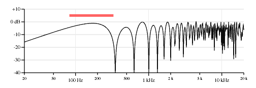
80% neck pickup, 20% bridge pickup. 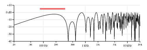
60% neck pickup, 40% bridge pickup. 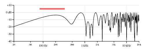
40% neck pickup, 60% bridge pickup. 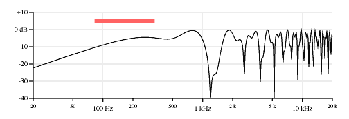
20% neck pickup, 80% bridge pickup.
Analysis of a two pickup mix
Here is the equation for the response of a single pickup from the previous article:
 Where:
Vpickup is the relative displacement velocity, and thus the relative pickup output level, at this point on the string. A value of 1.0 is the maximum.
Xpickup is the position of the pickup, the distance between the bridge and the center of the pickup in inches.
Fstring is the frequency of the vibrating string in Hz, whether the pitch is due to the fundamental or a harmonic of a fretted note or open string.
Lscale is the length of the open (unfretted) string in inches.
Fopen is the fundamental open (unfretted) frequency of the string in Hz.
This equation assumes the pickups are sensitive at a single point on the string; ie., the magnetic aperture is zero.
A 50/50 mix of two pickups at two different locations is a simple sum:

Where:V2pickups is the result of a 50/50 mix of two pickups signals, ie., an average of the two individual pickup responses.XpickupA and XpickupB are the positions of the two pickups, each in inches from the bridge.
Given the geometric equality:

And it's companion:

Adding them:

We can apply this to describe the response in terms of the average pickup position and the separation between the pickups as shown in Figure 4. This is very similar to the way one can describe the sum of two sine waves in terms of an average frequency and a beat frequency.


Where:XpickupAvg is the average of the positions of the two pickups in inches from the bridge.XpickupSep is the distance between the two pickups in inches.
So that:

Then we can substitute and put the equation for V2pickups in terms of XpickupAvg and XpickupSep:

(This equation is also described in the first Roland VG-8 patent as a digital implementation for emulating the sound of two pickups).
This equation is separable; the response of a 50/50 mix of two pickups can be described as two independent responses in series, one due to the average position of the two pickups and one due to the distance between them:

Where:VpickupAvg is the response of a single pickup located at position exactly between the two pickups.This is a cosine comb filter, a little different from the sine comb filter that is characteristic of a single pickup response. Response at DC will be unity instead of zero, and nulls will occur at odd multiples of the first null instead of at all multiples. This cosine response is proportional to the open string tuning just like the sine comb filter response of a single pickup.
i = 1, 3, 5...
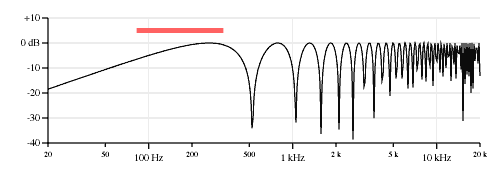
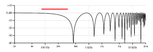
Figure 5 shows how the neck&bridge response can be split into these two components. The first response plot shows a copy of the neck&bridge response for reference, the second plot is the response of a pickup positioned at 4.0 inches from the bridge (the average of the two pickup locations), and the third plot shows the spectrum of the cosine comb filter effect of two pickups 4.75 inches apart from the above equation.
(Note that on a Stratocaster the middle pickup is positioned close to, but not exactly, the average of the neck and bridge locations.)
The nulls in the neck&bridge response are completely accounted for by the nulls in the other two responses. Thus there are nulls at 442.3 Hz, 525.3 Hz, 1051 Hz, 1327 Hz, 1576 Hz, 2101 Hz, 2212 Hz, 2627 Hz, 3096 Hz, 3152 Hz, etc. And peaks can be found between those nulls.

Neck and bridge pickups, opposite polarity
It is also possible to connect two pickups together with opposite polarity, swapping the wires or otherwise inverting the signal of one of the pickups so the pickups work against each other; the individual pickup signals subtract instead of add. Instruments like some Carvin models, the Fender Mustang, the Gibson Les Paul Recording and the Ovation Breadwinner/Deacon offered "out of phase" selections in their wiring. "Opposite polarity" is a more technically correct term than "out of phase", but I'm not picky. The plot looks like this:
As expected, since the signals are subtracting instead of reinforcing, the signal level of the frequencies below the first null are greatly diminished. There is also a big hump between the first two nulls of the neck pickup as the signals are in phase in that region. In this plot the hump is around 500 Hz.
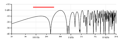
It is an interesting exercise to adjust the balance between the two pickups so that the open string fundamental cancels exactly. (And while it is an interesting excercise, some might not find a sound with no fundamental present to be musically useful.) As shown in the plots in Figure 7, small changes in the balance between the two pickups have very large effects on the timbre of the sound. Because of this effect I will claim that an opposite polarity pickup combination is seriously handicapped without control of the balance between the pickups. A wiring option on some Carvin models does this best because it has a polarity switch and a pickup balance control.
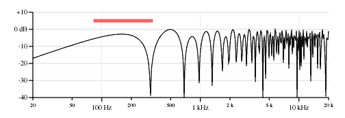
80% neck pickup, 20% bridge pickup, opposite polarity. 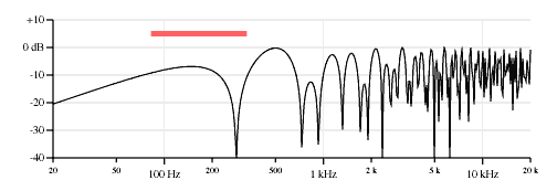
60% neck pickup, 40% bridge pickup, opposite polarity. 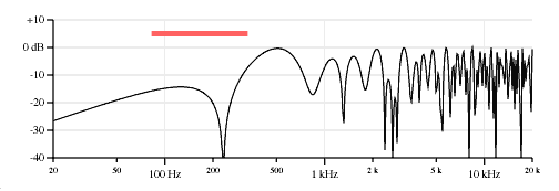
40% neck pickup, 60% bridge pickup, opposite polarity. 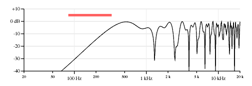
20% neck pickup, 80% bridge pickup, opposite polarity. 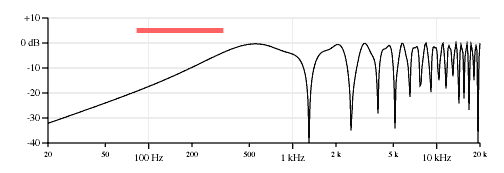
10% neck pickup, 90% bridge pickup, opposite polarity.
Analysis of two pickups, opposite polarity
Most of the previous analysis of the 50/50 mix of two pickups in phase applies to the opposite polarity situation.

Where:V2pickups180 is the result of a 50/50 mix of two pickups signals, opposite polarity.Given the same geometric equalities:

Subtracting them:

And applying this to the equation above:

Compare this to the previous equation for two pickups in phase:

It appears the numerators of the sine and cosine functions have just been swapped. It's a lovely symmetry but it doesn't make much sense, does it?
It turns out that this configuration is effectively the same as a mix of two pickups when one of the pickups is moved to a mirror image location on the other side of the bridge as shown in Figure 8. If the string vibration were continued on to the opposite side of the bridge it would be of opposite polarity. Then distance between the pickups becomes the sum of the two distances (or double the average pickup distance) and the average pickup distance becomes half the original distance between them. So the sum and difference measurements effectively swap positions.

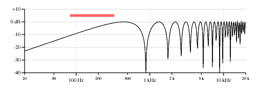
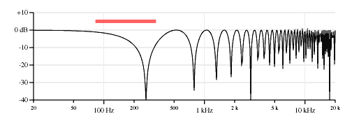
We can plot the components of this response as before. Figure 9 shows the neck&bridge opposite polarity response plot, then the response of a pickup 2.375 inches from the bridge, and then the effect of two pickups 8.0 inches apart. Again note how the nulls of the second and third plots describe the nulls in the first plot. (262.6 Hz, 787.8 Hz, 884.7 Hz, 1313 Hz, 1769 Hz, 1838 Hz, 2363 Hz, 2654 Hz, 2889 Hz, 3414 Hz, 3539 Hz, etc.)

Middle pickup combinations
Early Strat fans discovered it was possible to wedge the original Stratocaster's 3-position pickup selector switch in between the intended positions to get two additional pickup combinations. Since the switch was a shorting type, wedging the switch in between the neck and middle positions created a new neck&middle combination and wedging the switch between the middle and bridge positions created a new middle&bridge combination. Starting in 1978 Stratocasters were shipped with pickup selector switches featuring two additional detents for a total of five positions.
Both of these combination sounds had a distinctive nasal quality to them and were sometimes referred to as out of phase positions, not because the pickups were out of phase, they were not, but because the timbre was so different it demanded a descriptive name and the only remotely similar sound was the rarely heard out of phase combination only available on a few guitar models.
Figure 10 shows the response of the neck&middle combination with the average and separation components.
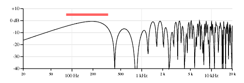
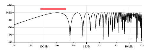

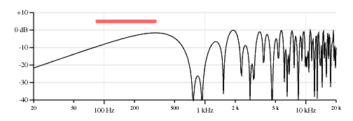
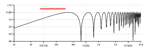
Figure 11 shows the response of the middle&bridge combination with the average and separation components.
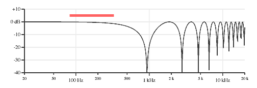
Three pickup combinations
Figure 12 shows the response plot for an even 33/33/33 mix of the neck, middle and bridge pickups.
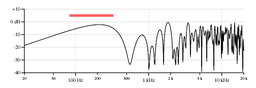
It's pretty complicated; I will not be going in an analysis of this here. However, you might be entertained by Figure 13, which shows plots of the possible combinations of even mixes of three pickups where one of the pickups of opposite polarity.
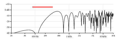
Neck, middle and bridge pickups, neck pickup opposite polarity. 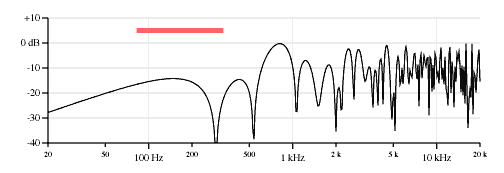
Neck, middle and bridge pickups, middle pickup opposite polarity. 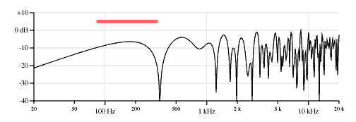
Neck, middle and bridge pickups, bridge pickup opposite polarity.
Conclusion
The same techniques of physical analysis for the response characteristics of an individual guitar pickup can be applied to the case of multiple pickups. Simple mixes of two pickups can provide a wide range of response curves, some suggesting the resonances of an acoustic instrument. For an even mix of two pickups a new response pattern emerges with separable dependancies on the average pickup position and separation between the pickups. Mixes of pickups with opposite polarity can be analyzed in a similar way. And a mix of three pickups can get pretty complex.
References
Response Effects of Guitar Pickup Position and Width, J. Donald Tillman. A companion to this article.Pickup Response Demonstration Applet, J. Donald Tillman, July 2000. A Java applet that graphically demonstrates pickup response curves.
US Patent 5,367,120:
Musical tone signal forming device for a stringed musical Instrument
Inventor: Atsushi Hoshiai
Assignee: Roland Corporation
Filed: 5 August 1992
Issued: 22 November 1994
Stratocaster is a trademark of Fender Musical Instruments Corp.