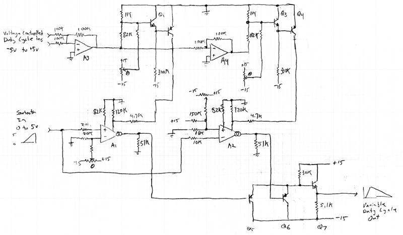
The power supply is +/- 15.0V. A1 and A2 are CA3280 OTAs. A3 and A4
are LF412 op amps. The transistors are reasonable high beta NPNs
and PNPs. The values for the trimming circuitry is intentionally
left off.
The basic idea is to take our rising sawtooth source and it's inverse,
a falling sawtooth from +5.0V to 0.0V, adjust the relative gains of
those two, and use the arithmetic minimum of those two signals as the
output. The gains would ideally go from 1.0 to infinity, but for
practical reasons I've limited the range to 1.11 through 10. If
the two gains are equal to 2.0 the output will be a triangle wave.
To keep the output amplitude constant the two gains should be such
that the sum of the recipricals of the gains is constant. And if
the output amplitude is going to be the same as the input amplitude,
that constant value needs to be unity.
To do this I rely on the equation:
1/(1 + ex) + 1/(1 + e-x) = 1
For this application, x is proportional to the duty cycle control
voltage, centered around zero for a 50% duty cycle.
1 + ex is proportional to one of the gains and
1 + e-x is proportional to the other. The
ex and e-x are implemented with simple ARP-style
exponential circuits, and the 1s in the denominators are currents
from resistors.
The signal path starts with the given sawtooth wave. A1 and A2
are set up run at 0.24 mA for a 50% duty cycle; we need plenty of
headroom to increase this gain, but the current for the lowest gain
still needs to drive the output to full amplitude.
The 82k resistors set the OTAs' input diode current to 170uA, for a
diode resistance of 416 ohms, for an input attenuation of 1/100th,
easily accomodating the input amplitude. From here, an OTA bias
current of 0.24mA (triangle wave) and the 51k ohm output resistor will
set the total gain to 2.0.
Transistors Q5 and Q6 are emitter followers with the lowest voltage
taking over. The output emitter follower compensates for the
offset voltage of the previous transistor two. Not exactly, but
close enough for now.
Op amp A3 creates mixes the input control voltages, op amp A4 provides
the negative. Both of these go to the ARP-style exponential
circuits. Adjust them to idle at 0.12mA each.
The 120kohm resistors are responsible for the 1s in the denominators
of the equation and the 4.7kohm resistors limit the control current
into the OTAs to a reasonble value.
No I haven't tested it yet. This is only a sketch and I'm
only publishing it here only to present it to the folks on synth-diy.
Correction: The resistor values on the inputs of A2 are wrong. They
should be, top to bottom, 62k, 39k, and 20k. They are supposed
to bias A2's input so the sawtooth effectively ramps down from 5.0
volts.
-- Don
