 A regular feature of
EDN Magazine is the Design Ideas
section, where readers contribute original circuit designs. Some
are good, some are silly, some are way esoteric, some are uses for a
device made, oddly enough, by the contributor's company.
The recent September 16 2004 issue has an fascinating entry,
"Diode
Compensates Distortion in Amplifier Stage" by S. Chekcheyev,
Pridnestrovye State University, Moldova. (Where???). He
takes a basic common-emitter amplifier circuit and is able to
compensate for the basic nonlinearities by adding a diode and a pair
of steering capacitors. This is really clever; I've never seen
anything like this before and I find it somewhat intriguing.
The classic transistor voltage gain stage, with the emitter grounded
through a bypass capacitor, has a transfer function that is
substantially exponential. If the input signal level is
sufficiently small the distortion might not be a problem, but for
larger signals the engineer would typically address the nonlinearities
with a resistor in series with the bypass cap, or no bypass cap, which
would apply local negative feedback and reduce the gain, or by
bringing in feedback from a later stage, or drive the input with more
of a current source than a voltage source, or any of a number of other
approaches.
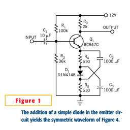
Here, he splits the emitter resistor and adds in a diode, so the diode
is running at the same current as the transistor, and then adds the
capacitors to route the audio signal around the diode in the opposite
direction. This way the dynamic resistance of the diode will
run opposite the dynamic gain of the transistor and effectively
compensate for most of the nonlinearity. Very clever.
I see a few problems with the circuit. At frequencies a little
below the -3dB low frequency cutoff, the capacitors will be mostly
removed from the circuit and the nonlinearity of the transistor will
be compounded with the nonlinearity of the diode. And the
circuit might not overload gracefully. And, those two 1000uF
capacitors are going to take up a lot of space. But it's still
a very interesting approach.
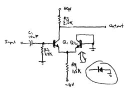
 Another way to think about the circuit is to make a roughly equivalent
version, adjusting the DC situation a little to eliminate the
caps. In this drawing I take the AC path from the emitter
through the diode and two caps to ground and replace it with the NPN
transistor equivalent of a diode to ground. The original +12.0 V
supply is split into +9.0 V and -6.0 V; the +9.0 is the difference
between the original power supply and original base voltage bias
point, and the -6.0V is double the original base voltage bias point
because now we need twice the current to run both transistors.
And yes, that's a standard differential amp. So S. Chekcheyev's
circuit could be considered the AC equivalent of a diff amp run
single-ended. (Roughly equivalent; they will overload slightly
differently.)
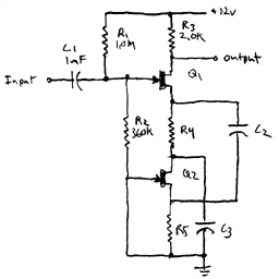
 Is it possible to make an FET version of S. Chekcheyev's
circuit? I think it would look something like this, with an FET
source follower performing the function of the diode. I have not
done an extensive analysis on it though.


 Another way to think about the circuit is to make a roughly equivalent
version, adjusting the DC situation a little to eliminate the
caps. In this drawing I take the AC path from the emitter
through the diode and two caps to ground and replace it with the NPN
transistor equivalent of a diode to ground. The original +12.0 V
supply is split into +9.0 V and -6.0 V; the +9.0 is the difference
between the original power supply and original base voltage bias
point, and the -6.0V is double the original base voltage bias point
because now we need twice the current to run both transistors.
 Is it possible to make an FET version of S. Chekcheyev's
circuit? I think it would look something like this, with an FET
source follower performing the function of the diode. I have not
done an extensive analysis on it though.